 由 Yaming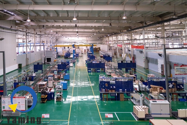
Inverter Production Line: Processes and Core Advantages
1. Production Line Overview
The inverter production line turns raw materials into finished products. These include household/commercial PV inverters and vehicle – mounted inverters. It follows a sequence: shell processing, core circuit assembly, power module integration, complete machine testing, and packaging. Using CNC systems, automated welding, and electrical testing tools, it enables flexible production of 1kW–100kW products. This meets diverse power needs across applications.
2. Shell Processing Line
As the inverter’s protective and heat – dissipation structure, the shell line focuses on “anti – corrosion + heat – dissipation adaptation”. First, CNC punching presses cut alloy or cold – rolled steel plates. This is based on inverter types (like household minicomputers or commercial mainframes). They reserve heat – dissipation holes, interface mounts, and fixing holes. The error margin is ±0.1mm to ensure component alignment. After CNC bending forms the shell frame, laser welding joins the sections. These sections are then polished. For surface treatment, alloy shells use anodic oxidation. Steel shells use electrostatic spraying. Both add a weather – resistant, insulating coating. A thermally conductive pad is pasted inside for heat transfer. Processed shells go to the assembly line. Batch info is tracked for quality traceability.
3. Core Circuit Assembly Line
Focused on “precision welding + insulation protection”, this line uses a segmented process: SMT chip mounting, plug – in soldering, and module integration. In the SMT phase, automated machines place micro – components (resistors, capacitors, chips) on PCBs. The accuracy is ±0.02mm. After welding, AOI equipment checks for defects (like misalignment or cold solder joints). Next, in the plug – in stage, workers use automatic machines to insert large components (transformers, inductors) into PCBs. These then undergo wave soldering for secure connections. Online Circuit Testing verifies circuit functionality and component parameters. Qualified PCBs form control/drive modules. They connect via shielded, insulated cables to prevent electromagnetic interference. Conveyor tracks reduce manual contact and damage risks.
4. Power Module Integration Line
Critical to inverter performance, this line prioritizes “power bridge installation + heat – dissipation optimization”. Workers use specialized tooling to install IGBTs, insulated – gate bipolar transistors, and rectifier bridges. They attach these to the housing with thermally conductive grease. Screws are tightened to an 8–12N·m torque for secure contact. Cables linking power and control modules use crimp terminals. This avoids overheating from high currents. During integration, power – loop insulation resistance is tested (needs ≥500MΩ). An infrared thermometer checks heat – dissipation contact of installed components. Unqualified modules are reworked right away to prevent performance issues.
5. Complete Machine Performance Testing Line
This line tests electrical performance, safety, and stability. Initial checks include visual inspections of appearance. Insulation resistance is measured with meters. Power testing follows: a platform simulates input voltages (e.g., PV array DC, 12V/24V vehicle – mounted DC). It verifies output accuracy (error ≤±1%), frequency stability (50Hz±0.5Hz), and conversion efficiency (≥96%). Safety tests cover overload protection (shutdown at 120% rated power), short – circuit resilience, and lightning protection. Environmental simulations (temperatures from – 30℃ to 70℃, high humidity) check operational stability. Test data uploads to the management system in real – time. Unqualified products go to maintenance. Qualified ones generate reports and move to packaging.
6. Finished Product Packaging and Storage Line
To protect precision components, inverters get automated dust – proof film wrapping. Then, they are packed into custom – sized cartons. Pearl cotton separators shield external interfaces and internal parts. Labels show model, power, production batch, and warnings (moisture – proof, anti – collision). After packaging, AGVs transport cartons to smart storage areas. Inverters are categorized by “power + application scenario” (e.g., separating household and vehicle – mounted units). The warehouse system updates inventory in real – time for quick order fulfillment. It also monitors temperature and humidity to avoid electrical performance problems.
7. Core Advantages
- Precision & Reliability: Key processes (SMT mounting, power integration, performance testing) have over 85% automation. Critical size errors stay within 0.1mm. Electrical testing covers 100% of parameters. This ensures inverter efficiency and safety from circuit to final assembly.
- Flexible Production: The line supports mixed production of inverters with different powers and uses. By replacing SMT programs and adjusting tooling, product switches finish in 2 hours. This meets diverse market demands.
- Intelligent Management: Integrated with an MES system, it collects real – time data (e.g., PCB welding yield, power test failure rates). It speeds up equipment fault warnings by 30%, enabling proactive issue fixing.

- If you have any questions or needs about the automated assembly line, please contact us via email: [email protected]